- Computer Graphics - Home
- Computer Graphics Basics
- Computer Graphics Applications
- Graphics APIs and Pipelines
- Computer Graphics Maths
- Sets and Mapping
- Solving Quadratic Equations
- Computer Graphics Trigonometry
- Computer Graphics Vectors
- Linear Interpolation
- Computer Graphics Devices
- Cathode Ray Tube
- Raster Scan Display
- Random Scan Device
- Phosphorescence Color CRT
- Flat Panel Displays
- 3D Viewing Devices
- Images Pixels and Geometry
- Color Models
- Line Generation
- Line Generation Algorithm
- DDA Algorithm
- Bresenham's Line Generation Algorithm
- Mid-point Line Generation Algorithm
- Circle Generation
- Circle Generation Algorithm
- Bresenham's Circle Generation Algorithm
- Mid-point Circle Generation Algorithm
- Ellipse Generation Algorithm
- Polygon Filling
- Polygon Filling Algorithm
- Scan Line Algorithm
- Flood Filling Algorithm
- Boundary Fill Algorithm
- 4 and 8 Connected Polygon
- Inside Outside Test
- 2D Transformation
- 2D Transformation
- Transformation Between Coordinate System
- Affine Transformation
- Raster Methods Transformation
- 2D Viewing
- Viewing Pipeline and Reference Frame
- Window Viewport Coordinate Transformation
- Viewing & Clipping
- Point Clipping Algorithm
- Cohen-Sutherland Line Clipping
- Cyrus-Beck Line Clipping Algorithm
- Polygon Clipping Sutherland–Hodgman Algorithm
- Text Clipping
- Clipping Techniques
- Bitmap Graphics
- 3D Viewing Transformation
- 3D Computer Graphics
- Parallel Projection
- Orthographic Projection
- Oblique Projection
- Perspective Projection
- 3D Transformation
- Rotation with Quaternions
- Modelling and Coordinate Systems
- Back-face Culling
- Lighting in 3D Graphics
- Shadowing in 3D Graphics
- 3D Object Representation
- Represnting Polygons
- Computer Graphics Surfaces
- Visible Surface Detection
- 3D Objects Representation
- Computer Graphics Curves
- Computer Graphics Curves
- Types of Curves
- Bezier Curves and Surfaces
- B-Spline Curves and Surfaces
- Data Structures For Graphics
- Triangle Meshes
- Scene Graphs
- Spatial Data Structure
- Binary Space Partitioning
- Tiling Multidimensional Arrays
- Color Theory
- Colorimetry
- Chromatic Adaptation
- Color Appearance
- Antialiasing
- Ray Tracing
- Ray Tracing Algorithm
- Perspective Ray Tracing
- Computing Viewing Rays
- Ray-Object Intersection
- Shading in Ray Tracing
- Transparency and Refraction
- Constructive Solid Geometry
- Texture Mapping
- Texture Values
- Texture Coordinate Function
- Antialiasing Texture Lookups
- Procedural 3D Textures
- Reflection Models
- Real-World Materials
- Implementing Reflection Models
- Specular Reflection Models
- Smooth-Layered Model
- Rough-Layered Model
- Surface Shading
- Diffuse Shading
- Phong Shading
- Artistic Shading
- Computer Animation
- Computer Animation
- Keyframe Animation
- Morphing Animation
- Motion Path Animation
- Deformation Animation
- Character Animation
- Physics-Based Animation
- Procedural Animation Techniques
- Computer Graphics Fractals
Phosphorescence and Color CRT in Computer Graphics
Raster scanning and random scanning devices draw images on phosphorcoated screens. There is a concept called Phosphorescence that helps in generating images on screen.
After monochrome images, Color CRTs came into being, where full colors are used in blending different phosphors that emit red, green, and blue light.
Read this chapter to learn the basics of phosphorescence, its role in CRT technology, and how color CRTs operate.
What is Phosphorescence?
Phosphorescence is the process with which phosphor materials emit light after being energized. These materials are exposed to radiation (such as ultraviolet light or an electron beam), they absorb energy and then slowly release it over time as visible light.
Unlike fluorescence, where the light emission stops almost immediately after the energy source is removed, phosphorescent materials continue to glow for some time after the initial excitation.
How Does Phosphorescence Work?
The process of phosphorescence can be explained in a few steps −
- Excitation − When energy (electron beams) hits a phosphorescent material, it excites the electrons in the material. The electrons move to higher energy bands.
- Energy Storage − After absorbing energy, the electrons are "trapped" in these higher energy states.
- Light Emission − Over time, the electrons slowly return to their original energy levels, releasing energy in the form of visible light. This delayed emission is what causes the material to continue glowing even after the energy source is removed.

The above curve is showing how the glow will get decayed over time. In CRT displays, phosphorescent materials are used to coat the inside of the screen. When the electron beam strikes the phosphor coating, it excites the phosphors, causing them to emit light.
Phosphorescence in CRTs
Since the glow of the phosphor coating is decaying, it must be reformed. But if we reform after complete decaying the result will flicker. So after some threshold when it decays, the same spot is energized again. This is shown in the following plot.

In color CRTs, three different phosphors are used, each emitting one of the primary colors: red, green, or blue. These colors mix to create the full-color display.
Color CRT
In color CRT, that also uses the principle of phosphorescence to produce color images. In a color CRT, the screen is coated with three types of phosphor dots: red, green, and blue. These three colors are the primary colors of light, and by combining them in various intensities, a full spectrum of colors can be displayed.

In the above diagram these are two patterns how image dots are placed on screen. However, there are several such patterns from different manufacturers.
Components of a Color CRT
A color CRT consists of several components that work together to produce the color images −
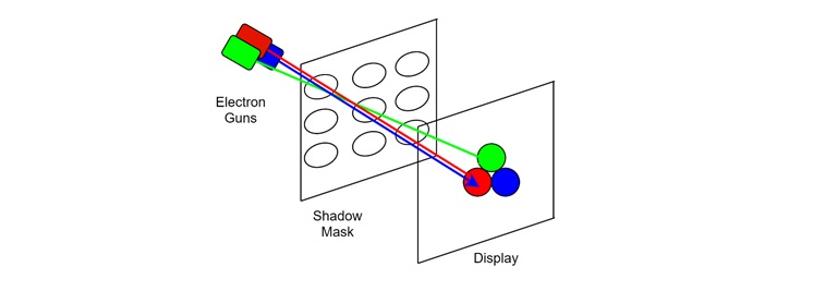
- Electron Guns − In a color CRT, there are three electron guns, one for each primary color: red, green, and blue. These electron guns generate beams of electrons that are directed toward the screen.
- Phosphor-Coated Screen − The screen is coated with tiny dots or stripes of as shown above of the colors red, green, and blue phosphors. These phosphors glow when struck by the electron beam, emitting light in their respective colors.
- Shadow Mask − Another important thing is the shadow mask. This is a metal plate with tiny holes that sits just in front of the phosphor-coated screen. It ensures that each electron beam only hits the correct set of phosphor dots. For example, the red electron beam only hits the red phosphor dots, while the green and blue beams hit their corresponding phosphors.
How Does a Color CRT Work?
A color CRT works by combining the light emitted from the red, green, and blue phosphors to create a full-color image.
- Electron Emission − The three electron guns emit beams of electrons, each targeting a different color phosphor on the screen.
- Electron Steering − The electron beams are directed toward specific areas of the screen using a deflection system, which moves the beams horizontally and vertically across the screen.
- Phosphor Activation − When the electron beams hit the red, green, and blue phosphor dots, the phosphors glow, emitting light in their respective colors.
- Color Mixing − The light from the red, green, and blue phosphors mixes to create the full range of colors visible on the screen. By controlling the intensity of each beam, the CRT can create different shades of color. For example, combining equal intensities of red, green, and blue produces white, while varying the intensities can create a range of colors.
Example of Color CRT in Televisions
One of the most common applications of color CRT technology was in televisions. In early color TVs, the CRT was responsible for displaying the video signal in full color. The television signal carried the information needed to control the intensity of the electron beams, which in turn controlled the brightness and color of each pixel on the screen.
For example, if the television signal indicated that a certain area of the screen should be blue, the blue electron gun would increase its intensity, while the red and green guns would decrease theirs. This allowed the screen to display the desired color in each area, creating a full-color image.
Advantages of Color CRTs
Given below are some of the advantages of Color CRTs −
- High Brightness and Contrast − Color CRTs can produce images with high brightness and contrast, making them suitable for a wide range of viewing conditions.
- Wide Viewing Angles − CRTs do not suffer from the limited viewing angles found in some early flat-panel displays. This means that the image remains clear and consistent even when viewed from an angle.
- Smooth Color Transitions − The ability to mix red, green, and blue light allows CRTs to create smooth color transitions and gradients, resulting in more realistic images.
Disadvantages of Color CRTs
Following are some of the disadvantages of Color CRTs −
- Bulky and Heavy − Color CRTs are large and heavy, heavier than monochrome displays. Larger screen sizes. This makes them less practical for modern devices
- High Power Consumption − CRTs consume more power compared to modern display technologies, making them less energy efficient.
- Flickering − If the refresh rate is too low, CRTs can produce flickering, which can lead to eye strain over time.
Conclusion
In this chapter, we explained the concepts of phosphorescence and color CRT technology. We discussed how phosphorescent materials are used in CRT displays to produce light, and how color CRTs use red, green, and blue phosphors to create full-color images.
We also covered how the components of a color CRT such as electron guns and the shadow mask work together to produce a clear and effective image.