- Computer Graphics - Home
- Computer Graphics Basics
- Computer Graphics Applications
- Graphics APIs and Pipelines
- Computer Graphics Maths
- Sets and Mapping
- Solving Quadratic Equations
- Computer Graphics Trigonometry
- Computer Graphics Vectors
- Linear Interpolation
- Computer Graphics Devices
- Cathode Ray Tube
- Raster Scan Display
- Random Scan Device
- Phosphorescence Color CRT
- Flat Panel Displays
- 3D Viewing Devices
- Images Pixels and Geometry
- Color Models
- Line Generation
- Line Generation Algorithm
- DDA Algorithm
- Bresenham's Line Generation Algorithm
- Mid-point Line Generation Algorithm
- Circle Generation
- Circle Generation Algorithm
- Bresenham's Circle Generation Algorithm
- Mid-point Circle Generation Algorithm
- Ellipse Generation Algorithm
- Polygon Filling
- Polygon Filling Algorithm
- Scan Line Algorithm
- Flood Filling Algorithm
- Boundary Fill Algorithm
- 4 and 8 Connected Polygon
- Inside Outside Test
- 2D Transformation
- 2D Transformation
- Transformation Between Coordinate System
- Affine Transformation
- Raster Methods Transformation
- 2D Viewing
- Viewing Pipeline and Reference Frame
- Window Viewport Coordinate Transformation
- Viewing & Clipping
- Point Clipping Algorithm
- Cohen-Sutherland Line Clipping
- Cyrus-Beck Line Clipping Algorithm
- Polygon Clipping Sutherland–Hodgman Algorithm
- Text Clipping
- Clipping Techniques
- Bitmap Graphics
- 3D Viewing Transformation
- 3D Computer Graphics
- Parallel Projection
- Orthographic Projection
- Oblique Projection
- Perspective Projection
- 3D Transformation
- Rotation with Quaternions
- Modelling and Coordinate Systems
- Back-face Culling
- Lighting in 3D Graphics
- Shadowing in 3D Graphics
- 3D Object Representation
- Represnting Polygons
- Computer Graphics Surfaces
- Visible Surface Detection
- 3D Objects Representation
- Computer Graphics Curves
- Computer Graphics Curves
- Types of Curves
- Bezier Curves and Surfaces
- B-Spline Curves and Surfaces
- Data Structures For Graphics
- Triangle Meshes
- Scene Graphs
- Spatial Data Structure
- Binary Space Partitioning
- Tiling Multidimensional Arrays
- Color Theory
- Colorimetry
- Chromatic Adaptation
- Color Appearance
- Antialiasing
- Ray Tracing
- Ray Tracing Algorithm
- Perspective Ray Tracing
- Computing Viewing Rays
- Ray-Object Intersection
- Shading in Ray Tracing
- Transparency and Refraction
- Constructive Solid Geometry
- Texture Mapping
- Texture Values
- Texture Coordinate Function
- Antialiasing Texture Lookups
- Procedural 3D Textures
- Reflection Models
- Real-World Materials
- Implementing Reflection Models
- Specular Reflection Models
- Smooth-Layered Model
- Rough-Layered Model
- Surface Shading
- Diffuse Shading
- Phong Shading
- Artistic Shading
- Computer Animation
- Computer Animation
- Keyframe Animation
- Morphing Animation
- Motion Path Animation
- Deformation Animation
- Character Animation
- Physics-Based Animation
- Procedural Animation Techniques
- Computer Graphics Fractals
Raster Scan Display in Computer Graphics
Raster scanning is a fundamental concept in computer graphics and display technology. It is used to draw an image line by line from top to bottom on a screen. This method has been widely used in television, computer monitors, and other digital displays.
Read this chapter to learn the basic concept of raster scan, how it works, and the differences between progressive scanning and interlaced scanning. We will also cover real-world examples for a better understanding.
What is Raster Scanning?
While studying CRT, one question comes to our mind that how CRT forms images, because we understood how CRT could produce a single dot on screen. The answer is using raster scanning. This process draws images on display area line by line.
A display screen is divided into a grid of pixels, and each line of pixels is called a scanline. The electron beam in a cathode ray tube (CRT) or the display controller in modern screens moves across each line, lighting up pixels to form an image.
How Does Raster Scanning Work?
Raster scanning works by breaking down an image into horizontal lines of pixels. Each pixel holds information about color and brightness.
The scanning process follows a specific sequence −
- Horizontal Scan − The display starts from the top-left corner and moves horizontally across the screen, lighting up the necessary pixels along the way.
- Vertical Retrace − Once the beam reaches the end of a line, it quickly returns to the left side of the screen, one line below, to start scanning the next row of pixels. This process continues until the entire screen is drawn, from the top to the bottom.
- Frame Completion − After completing all the scanlines, the screen displays a full image or frame. In a fast enough system, this happens many times per second, creating a smooth and continuous image.
Refresh Rate and Frames
Another interesting concept associated with raster scanning is the refresh rate. This is the number of times the screen redraws the image per second. It is typically measured in Hertz (Hz). A higher refresh rate makes the displayed image smoother and reduces flickering.
In older CRTs, the refresh rate was a critical factor in reducing flicker, while modern displays with higher refresh rates are preferred for gaming and video playback.
Types of Scanning
Based on raster scanning there are two primary methods of scanning and video display technologies. These are progressive scanning and interlaced scanning. Each has its own advantages and is suited for different applications.
- Progressive Scanning
- Interlaced Scanning
What is Progressive Scanning?
Progressive scanning is a method where the entire image is drawn on the screen in a single pass, line by line from top to bottom. In this approach, each frame consists of all the lines or scanlines displayed in sequence. As a result, the image is displayed without any interruptions or breaks.

See this image, here black lines are forming images. From left to right. After completing a line, it moves to the next line below the current line. The grey dashed line shows moving to next line. This is called horizontal retrace. After completing the entire screen, it jumps back to top left (shown in red color, this is vertical retrace)
However due to phosphorescence effect, when the scan line comes downward, the upper lines stars fading and images are not as bright as before. For that another scanning technique has arrived.
What is Interlaced Scanning?
Interlaced scanning, on the other hand, divides the frame into two fields. Each field contains half of the image, with the odd-numbered lines in the first field and the even-numbered lines in the second field. The fields are displayed alternately, so the screen refreshes twice for every full frame.
How Does Interlaced Scanning Work?
In interlaced scanning, the first pass of the electron beam or display controller draws the odd-numbered lines of the image, starting from the top and skipping every second line. The second pass then fills in the even-numbered lines, completing the image.
By interleaving the two fields, the display can create the illusion of a higher refresh rate without transmitting as much data.
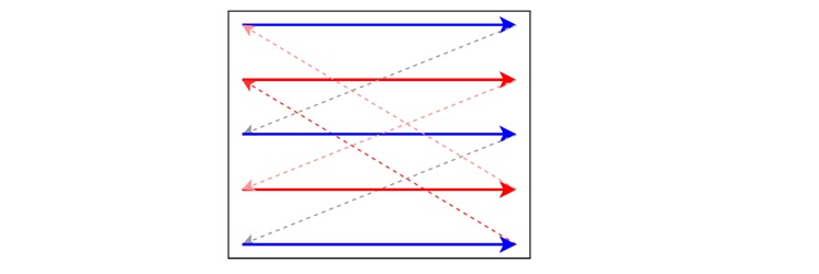
Here, the blue lines are odd lines and the red lines are even lines. Starting from odd lines and horizontal retrace (grey dashed lines) it reaches at the bottom. But now, the vertical retrace is not sending to the previous top-left line, it moves to the even lines. Now same happens and horizontal retrace is happening with red dashed lines. Finally after completing the entire pass it moves to top-left corner to start again.
Difference between Progressive Scanning and Interlaced Scanning
The following table compares and contrasts the important features of Interlaced Scanning and Progressive Scanning −
| Interlaced Scan | Progressive Scan |
|---|---|
| Interlaced scan is a scanning technique where one frame is divided into multiple scans. | In a progressive scan, scanning occurs by promptly scanning all frames. |
| The interlaced scan is generally considered less efficient than the progressive scan. | Progressive scan is considered more efficient than interlaced scan. |
| The video speed displayed in interlaced scan is lower than that of progressive scan. | Progressive scan displays video faster than interlaced scan. |
| The interlaced scan exhibits a combing effect. | The progressive scan does not exhibit any combing effect. |
| The video quality is vulgarized in interlaced scan. | Progressive scan offers superior video quality compared to interlaced scan. |
Advantages of Raster Scan
Raster scanning is relatively simple and can be easily implemented in hardware and software. It is a well-understood technology, and many display devices are optimized for raster scans.
Since most images are stored in raster format (a grid of pixels), raster scanning works well with digital images. It is compatible with a wide range of input formats and video standards.
Disadvantages of Raster Scan
Raster scanning, particularly with progressive scan, can require significant bandwidth to transmit all the image data. This can be a limiting factor in certain applications, especially when dealing with high-definition content.
Interlaced scanning, while saving bandwidth, can introduce visual artifacts such as blurring or flickering, which reduce image quality.
Conclusion
In this chapter, we covered the concept of raster scanning and its importance in computer graphics and display technology. We explained how raster scans work by dividing the screen into horizontal lines of pixels, which are drawn line by line to create an image.
In addition, we highlighted the two main types of scanning: progressive scanning where the entire frame is drawn in one pass, and interlaced scanning that splits the frame into two fields. Both methods have their own advantages and limitations. Progressive scanning offers smoother motion and higher image quality, while interlaced scanning conserves bandwidth but introduces motion artifacts.