- Electrical Machines - Home
- Basic Concepts
- Electromechanical Energy Conversion
- Energy Stored in Magnetic Field
- Singly-Excited and Doubly Excited Systems
- Rotating Electrical Machines
- Electrical Machines Types
- Faraday’s Laws of Electromagnetic Induction
- Concept of Induced EMF
- Fleming's Left Hand and Right Hand Rules
- Transformers
- Electrical Transformer
- Construction of Transformer
- EMF Equation of Transformer
- Turns Ratio and Voltage Transformation Ratio
- Ideal Transformer
- Practical Transformer
- Ideal and Practical Transformers
- Transformer on DC
- Losses in a Transformer
- Efficiency of Transformer
- 3-Phase Transformer
- Types of Transformers
- More on Transformers
- Transformer Working Principle
- Single-Phase Transformer Working Principle
- 3-Phase Transformer Principle
- 3-Phase Induction Motor Torque-Slip
- 3-Phase Induction Motor Torque-Speed
- 3-Phase Transformer Harmonics
- Double-Star Connection (3-6 Phase)
- Double-delta Connection (3-6 Phase)
- Transformer Ratios
- Voltage Regulation
- Delta-Star Connection (3-Phase)
- Star-Delta Connection (3-Phase)
- Autotransformer Conversion
- Back-to-back Test (Sumpner's Test)
- Transformer Voltage Drop
- Autotransformer Output
- Open and Short Circuit Test
- 3-Phase Autotransformer
- Star-Star Connection
- 6-Phase Diametrical Connections
- Circuit Test (Three-Winding)
- Potential Transformer
- Transformers Parallel Operation
- Open Delta (V-V) Connection
- Autotransformer
- Current Transformer
- No-Load Current Wave
- Transformer Inrush Current
- Transformer Vector Groups
- 3 to 12-Phase Transformers
- Scott-T Transformer Connection
- Transformer kVA Rating
- Three-Winding Transformer
- Delta-Delta Connection Transformer
- Transformer DC Supply Issue
- Equivalent Circuit Transformer
- Simplified Equivalent Circuit of Transformer
- Transformer No-Load Condition
- Transformer Load Condition
- OTI WTI Transformer
- CVT Transformer
- Isolation vs Regular Transformer
- Dry vs Oil-Filled
- DC Machines
- Construction of DC Machines
- Types of DC Machines
- Working Principle of DC Generator
- EMF Equation of DC Generator
- Derivation of EMF Equation DC Generator
- Types of DC Generators
- Working Principle of DC Motor
- Back EMF in DC Motor
- Types of DC Motors
- Losses in DC Machines
- Applications of DC Machines
- More on DC Machines
- DC Generator
- DC Generator Armature Reaction
- DC Generator Commutator Action
- Stepper vs DC Motors
- DC Shunt Generators Critical Resistance
- DC Machines Commutation
- DC Motor Characteristics
- Synchronous Generator Working Principle
- DC Generator Characteristics
- DC Generator Demagnetizing & Cross-Magnetizing
- DC Motor Voltage & Power Equations
- DC Generator Efficiency
- Electric Breaking of DC Motors
- DC Motor Efficiency
- Four Quadrant Operation of DC Motors
- Open Circuit Characteristics of DC Generators
- Voltage Build-Up in Self-Excited DC Generators
- Types of Armature Winding in DC Machines
- Torque in DC Motors
- Swinburne’s Test of DC Machine
- Speed Control of DC Shunt Motor
- Speed Control of DC Series Motor
- DC Motor of Speed Regulation
- Hopkinson's Test
- Permanent Magnet DC Motor
- Permanent Magnet Stepper Motor
- DC Servo Motor Theory
- DC Series vs Shunt Motor
- BLDC Motor vs PMSM Motor
- Induction Motors
- Introduction to Induction Motor
- Single-Phase Induction Motor
- 3-Phase Induction Motor
- Construction of 3-Phase Induction Motor
- 3-Phase Induction Motor on Load
- Characteristics of 3-Phase Induction Motor
- Speed Regulation and Speed Control
- Methods of Starting 3-Phase Induction Motors
- More on Induction Motors
- 3-Phase Induction Motor Working Principle
- 3-Phase Induction Motor Rotor Parameters
- Double Cage Induction Motor Equivalent Circuit
- Induction Motor Equivalent Circuit Models
- Slip Ring vs Squirrel Cage Induction Motors
- Single-Cage vs Double-Cage Induction Motor
- Induction Motor Equivalent Circuits
- Induction Motor Crawling & Cogging
- Induction Motor Blocked Rotor Test
- Induction Motor Circle Diagram
- 3-Phase Induction Motors Applications
- 3-Phase Induction Motors Torque Ratios
- Induction Motors Power Flow Diagram & Losses
- Determining Induction Motor Efficiency
- Induction Motor Speed Control by Pole-Amplitude Modulation
- Induction Motor Inverted or Rotor Fed
- High Torque Cage Motors
- Double-Cage Induction Motor Torque-Slip Characteristics
- 3-Phase Induction Motors Starting Torque
- 3-phase Induction Motor - Rotor Resistance Starter
- 3-phase Induction Motor Running Torque
- 3-Phase Induction Motor - Rotating Magnetic Field
- Isolated Induction Generator
- Capacitor-Start Induction Motor
- Capacitor-Start Capacitor-Run Induction Motor
- Winding EMFs in 3-Phase Induction Motors
- Split-Phase Induction Motor
- Shaded Pole Induction Motor
- Repulsion-Start Induction-Run Motor
- Repulsion Induction Motor
- PSC Induction Motor
- Single-Phase Induction Motor Performance Analysis
- Linear Induction Motor
- Single-Phase Induction Motor Testing
- 3-Phase Induction Motor Fault Types
- Synchronous Machines
- Introduction to 3-Phase Synchronous Machines
- Construction of Synchronous Machine
- Working of 3-Phase Alternator
- Armature Reaction in Synchronous Machines
- Output Power of 3-Phase Alternator
- Losses and Efficiency of an Alternator
- Losses and Efficiency of 3-Phase Alternator
- Working of 3-Phase Synchronous Motor
- Equivalent Circuit and Power Factor of Synchronous Motor
- Power Developed by Synchronous Motor
- More on Synchronous Machines
- AC Motor Types
- Induction Generator (Asynchronous Generator)
- Synchronous Speed Slip of 3-Phase Induction Motor
- Armature Reaction in Alternator at Leading Power Factor
- Armature Reaction in Alternator at Lagging Power Factor
- Stationary Armature vs Rotating Field Alternator Advantages
- Synchronous Impedance Method for Voltage Regulation
- Saturated & Unsaturated Synchronous Reactance
- Synchronous Reactance & Impedance
- Significance of Short Circuit Ratio in Alternator
- Hunting Effect Alternator
- Hydrogen Cooling in Synchronous Generators
- Excitation System of Synchronous Machine
- Equivalent Circuit Phasor Diagram of Synchronous Generator
- EMF Equation of Synchronous Generator
- Cooling Methods for Synchronous Generators
- Assumptions in Synchronous Impedance Method
- Armature Reaction at Unity Power Factor
- Voltage Regulation of Alternator
- Synchronous Generator with Infinite Bus Operation
- Zero Power Factor of Synchronous Generator
- Short Circuit Ratio Calculation of Synchronous Machines
- Speed-Frequency Relationship in Alternator
- Pitch Factor in Alternator
- Max Reactive Power in Synchronous Generators
- Power Flow Equations for Synchronous Generator
- Potier Triangle for Voltage Regulation in Alternators
- Parallel Operation of Alternators
- Load Sharing in Parallel Alternators
- Slip Test on Synchronous Machine
- Constant Flux Linkage Theorem
- Blondel's Two Reaction Theory
- Synchronous Machine Oscillations
- Ampere Turn Method for Voltage Regulation
- Salient Pole Synchronous Machine Theory
- Synchronization by Synchroscope
- Synchronization by Synchronizing Lamp Method
- Sudden Short Circuit in 3-Phase Alternator
- Short Circuit Transient in Synchronous Machines
- Power-Angle of Salient Pole Machines
- Prime-Mover Governor Characteristics
- Power Input of Synchronous Generator
- Power Output of Synchronous Generator
- Power Developed by Salient Pole Motor
- Phasor Diagrams of Cylindrical Rotor Moto
- Synchronous Motor Excitation Voltage Determination
- Hunting Synchronous Motor
- Self-Starting Synchronous Motor
- Unidirectional Torque Production in Synchronous Motor
- Effect of Load Change on Synchronous Motor
- Field Excitation Effect on Synchronous Motor
- Output Power of Synchronous Motor
- Input Power of Synchronous Motor
- V Curves & Inverted V Curves of Synchronous Motor
- Torque in Synchronous Motor
- Construction of 3-Phase Synchronous Motor
- Synchronous Motor
- Synchronous Condenser
- Power Flow in Synchronous Motor
- Types of Faults in Alternator
- Miscellaneous Topics
- Electrical Generator
- Determining Electric Motor Load
- Solid State Motor Starters
- Characteristics of Single-Phase Motor
- Types of AC Generators
- Three-Point Starter
- Four-Point Starter
- Ward Leonard Speed Control Method
- Pole Changing Method
- Stator Voltage Control Method
- DOL Starter
- Star-Delta Starter
- Hysteresis Motor
- 2-Phase & 3-Phase AC Servo Motors
- Repulsion Motor
- Reluctance Motor
- Stepper Motor
- PCB Motor
- Single-Stack Variable Reluctance Stepper Motor
- Schrage Motor
- Hybrid Schrage Motor
- Multi-Stack Variable Reluctance Stepper Motor
- Universal Motor
- Step Angle in Stepper Motor
- Stepper Motor Torque-Pulse Rate Characteristics
- Distribution Factor
- Electrical Machines Basic Terms
- Synchronizing Torque Coefficient
- Synchronizing Power Coefficient
- Metadyne
- Motor Soft Starter
- CVT vs PT
- Metering CT vs Protection CT
- Stator and Rotor in Electrical Machines
- Electric Motor Winding
- Electric Motor
- Useful Resources
- Quick Guide
- Resources
- Discussion

Electrical Machines Tutorial
Electrical Machines Tutorial
Electrical Machines are electromagnetic devices designed to convert electrical energy into mechanical energy and vice-versa. Electrical machines are studied as a core subject in the electrical engineering discipline. It is included in the syllabus of electrical engineering to understand the design, principle, operation, and applications of various electrical machines like generators, motors, transformers, etc. which are very important for electrical engineers.

Electrical machines are the fundamental components of modern engineering and industries. In the domain of electrical engineering, it is very crucial to master the concepts of electrical machines because they pave the path for power generation, operation of machinery, and energy conversion.
This tutorial on electrical machines is written at a somewhat basic level and is intended for those who do not necessarily have a background in electrical engineering and electrical machines. Thus, it may be used as an introductory resource on electrical machines for undergraduate college students as well as a reference for practicing electrical engineers.
What are Electrical Machine?
An electrical machine is an electromagnetic device that either converts electrical energy into mechanical energy (electric motor) or converts mechanical energy into electrical energy (electric generator).
A transformer is a special electrical machine that does not covert electrical energy into mechanical energy and vice-versa, instead it transforms the voltage levels of electrical energy. The operations of all electrical machines are based on the mutual interaction of electric and magnetic fields. Hence, they are called electromagnetic machines.
Electrical machines can be classified into various types depending on their functions, supply used, for example, induction motor, synchronous motor, transformer, dc motor, dc generator, alternator, etc.
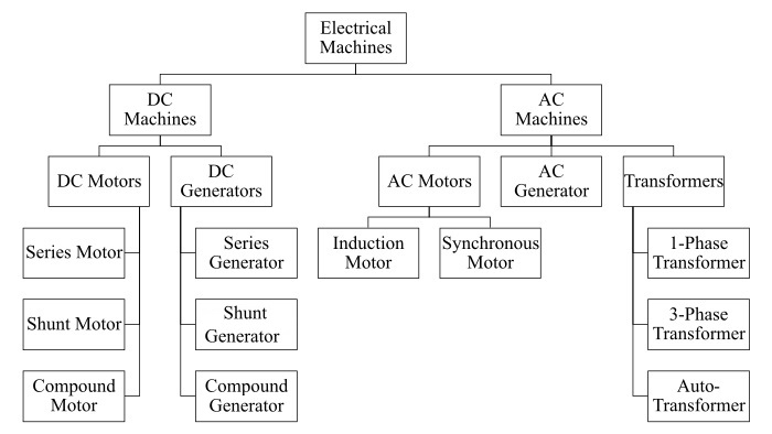
Types of Electrical Machines
Electrical machines can be classified into various types. The detailed main types of electrical machines is shown in the following figure.
Outline of This Tutorial
The main objective of Electrical Machines is to provide an overview of the range of concepts of electrical machines, and principle and applications of various electrical machines. The understanding these concepts is very important to perform jobs related to electrical machine design, operation, and maintenance.
This tutorial on "Electrical Machines" is divided into six modules −
The first module covers the basic concepts related to electrical machines that includes topics like principle of −
- Electromechanical Energy Conversion
- Energy Stored in a Magnetic Field
- Singly-Excited and Doubly Excited Systems
- Rotating Electrical Machines
- Faradays Laws of Electromagnetic Induction
- Concept of Induced EMF
- Flemings Left Hand and Right Hand Rules
The second module covers the theory of electrical transformer like −
- Electrical Transformer
- Construction of Transformer
- EMF Equation of Transformer
- Turns Ratio and Voltage Transformation Ratio
- Ideal and Practical Transformers
- Transformer on DC
- Losses in a Transformer
- Efficiency of Transformer
- Three-Phase Transformer
- Types of Transformers
The third module covers the concepts of DC machines such as −
- Construction of DC Machines
- Types of DC Machines
- Working Principle of DC Generator
- EMF Equation of DC Generator
- Types of DC Generators
- Working Principle of DC Motor
- Back EMF in DC Motor
- Types of DC Motors
- Losses in DC Machines
- Applications of DC Machines
The fourth module covers the concepts related to induction motors like −
- Introduction to Induction Motor
- Single-Phase Induction Motor
- Three-Phase Induction Motor
- Construction of Three-Phase Induction Motor
- Three-Phase Induction Motor on Load
- Characteristics of 3-Phase Induction Motor
- Speed Regulation and Speed Control
- Methods of Starting 3-Phase Induction Motors
The fifth module explains the synchronous machines including its −
- Introduction to 3-Phase Synchronous Machines
- Construction of Synchronous Machine
- Working of 3-Phase Alternator
- Armature Reaction in Synchronous Machines
- Output Power of 3-Phase Alternator
- Losses and Efficiency of 3-Phase Alternator
- Working of 3-Phase Synchronous Motor
- Equivalent Circuit and Power Factor of Synchronous Motor
- Power Developed by Synchronous Motor
The sixth module of this tutorial provides useful resources, a quick guide, and community discussion platform on electrical machines.
What does an Electrical Transformer Do?
An electrical transformer increases or decreases the voltage levels in an electrical power system. A transformer that increases the voltage level (i.e., output voltage is greater than input voltage) is known as a step-up transformer. A transformer that decreases the voltage level (i.e., output voltage is less than input voltage) is known as a step-down transformer.
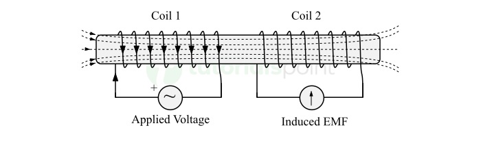
Working Principle of a Transformer
An electrical transformer works on the principle of mutual inductance. The principle of mutual inductance states that when two electromagnetic coils are brought near to each other such the magnetic field produced by one coil links with the other. If this linked magnetic field produced by first coil changes, then it induces an EMF in the second coil. This principle is highlighted in the following figure.
Are transformers AC or DC?
Transformers are AC devices. An electrical transformer cannot operate on DC supply because transformer requires changing magnetic flux for its operation which can be only produced by AC supply.
Types of Electrical Motor
An electric motor is an electromechanical energy conversion device that converts electrical energy into mechanical energy. Electric motors can be classified into various types as follows −
1. DC Motors
Those electric motors that convert direct current electricity into mechanical energy are known as DC motors. DC motors are further classified into the following types −
- DC Series Motor − A DC motor in which armature winding and magnetic field winding are connected in series with each other is called a DC series motor.
- DC Shunt Motor − A DC motor in which armature and field windings are connected in parallel with each other is called a DC shunt motor.
-
DC Compound Motor − A DC compound motor is one which consists of both series and shunt field winding is called a compound DC motor. There are two types of compound DC motors, which are −
- Cumulatively Compound DC Motor − When shunt and series fields assist each other, then the motor is called a cumulatively compound dc motor.
- Differentially Compound DC Motor − When the shunt and series fields oppose each other, then the motor is called a differentially compound dc motor.
2. AC Motors
Those electric motors that require alternating current supply to produce mechanical energy are called AC motors. There are two main types of AC motors namely,
- Induction Motor − An induction motor is a type of AC electric motor that operates on the principle of continuous electromagnetic induction. Induction motors can be classified as single-phase induction motors and three-phase induction motors.
- Synchronous Motor − A synchronous motor is also a type of AC motor that operates on the principle of magnetic locking, where the rotor is locked with the stators rotating magnetic field and rotates at the synchronous speed (i.e., speed of rotating magnetic field).
Prerequisites to Understand Electrical Machines
As with most introductory electrical machine tutorial, the main prerequisites are a basic understanding of physics and mathematics. However, it will definitely help if you are familiar with the fundamental concepts of electric and magnetic circuits.
FAQs on Electrical Machines
We have collected here a set of Frequently Asked Questions (FAQs) on Electrical Machines, followed by their answers.
The main function of an electric motor is to convert input electrical energy into rotational mechanical energy and drive mechanical loads.
An electric generator is an electromechanical energy conversion device that converts mechanical energy into electrical energy. The output of an electric generator is electric supply that can be either AC or DC, depending on the type of generator.
The main function of a generator is to produce electricity. In other words, an electric generator performs the conversion of mechanical energy into electrical energy.
An electric generator produces electricity through electromagnetic induction. A generator consists of an armature winding and a rotating magnetic field winding. When the magnetic field of rotating winding links to the armature winding (stationary), due to rotation, the magnetic field linked to the armature winding changes
According to the principle of electromagnetic induction, an EMF is induced in the armature winding. This induced EMF causes a potential difference at the ends of the armature winding. This is how a generator produces electricity.
It depends on the type of generator, i.e., a generator can generate AC as well as DC.
The generator that produces alternating current output is called an AC generator. The generator that generates direct current electricity is called a DC generator.
Alternator is nothing but an electric generator that produced alternating current electricity. Therefore, the main function of an alternator is to produce AC electricity.
A synchronous machine, either motor or generator, is a rotating electrical machine whose rotor rotates at the same speed as the rotating magnetic field do, i.e., synchronous speed.
If the machine is a generator, then it is called a synchronous generator. If the machine is a motor, then it is referred to as a synchronous motor.
Synchronous and asynchronous machines are the types of rotating electrical machines used for electromechanical energy conversion.
A synchronous machine is one that operates at the synchronous speed (i.e., speed of the rotating magnetic field), while an asynchronous machine is an electrical machine that can never operate at the synchronous speed but always runs at a speed slightly lower than the synchronous speed. Asynchronous machines are also known induction machines.
An induction motor is said be an induction motor because it requires continuous electromagnetic induction for its operation. If electromagnetic induction dies in the motor, the motor stops instantly.
The working principle of induction motor is based on the principle of electromagnetic induction and interaction of electric and magnetic field. According to these principles when a rotating or changing magnetic field links to a conductor, an EMF is induced in the conductor.
If the conductor is in a closed circuit, an electric current start flowing through it. Now, the current carrying conductor is located in a magnetic field and experiences an electromagnetic force and moves in a certain direction.
A rotating electrical machine is nothing but an electromechanical energy conversion device that consists of two parts namely, stator and rotor. It is called a rotating electrical machine because its rotor is free to move or rotate on its own axis. Electric generators and motors are known as the rotating electrical machines.
An electrical transformer is used for the following purposes −
- To increase or decrease the voltage levels in power system.
- To provide electrical isolation between two electric circuits.
- To provide magnetic coupling between two electric circuit.
- For measurement and protection purposes in high-voltage power networks.
A singly excited motor is a type of electric motor in which only a single coil is used to produce magnetic field. Thus, a singly-excited motor consists of only one electrical input and one mechanical output. A common example of singly-excited motor is an induction motor.
A doubly-excited motor is a type of electric motor which consists of two separately excited coils to produce magnetic fields. Hence, in a doubly-excited motor, there is two electrical inputs and one mechanical output. A common example of doubly excited motor is a synchronous motor.