- Data Comm & Networks Home
- DCN - Overview
- DCN - What is Computer Network
- DCN - Uses of Computer Network
- DCN - Computer Network Types
- DCN - Network LAN Technologies
- DCN - Computer Network Models
- DCN - Computer Network Security
- DCN - Components
- DCN - Connectors
- DCN - Switches
- DCN - Repeaters
- DCN - Gateways
- DCN - Bridges
- DCN - Socket
- DCN - Network Interface Card
- DCN - NIC: Pros and Cons
- DCN - Network Hardware
- DCN - Network Port
- Computer Network Topologies
- DCN - Computer Network Topologies
- DCN - Point-to-point Topology
- DCN - Bus Topology
- DCN - Star Topology
- DCN - Ring Topology
- DCN - Mesh Topology
- DCN - Tree Topology
- DCN - Hybrid Topology
- Physical Layer
- DCN - Physical Layer Introduction
- DCN - Digital Transmission
- DCN - Analog Transmission
- DCN - Transmission media
- DCN - Wireless Transmission
- DCN - Transmission Impairments
- DCN - Multiplexing
- DCN - Network Switching
- Data Link Layer
- DCN - Data Link Layer Introduction
- DCN - Data Link Control & Protocols
- DCN - RMON
- DCN - Token Ring Network
- DCN - Hamming Code
- DCN - Byte Stuffing
- DCN - Channel Allocation
- DCN - MAC Address
- DCN - Cyclic Redundancy Checks
- DCN - Error Control
- DCN - Flow Control
- DCN - Framing
- DCN - Error Detection & Correction
- DCN - Error Correcting Codes
- DCN - Parity Bits
- Network Layer
- DCN - Network Layer Introduction
- DCN - Network Addressing
- DCN - Routing
- DCN - Internetworking
- DCN - Network Layer Protocols
- DCN - Routing Information Protocol
- DCN - Border Gateway Protocol
- DCN - OSPF Protocol
- DCN - Network Address Translation
- DCN - Network Address Translation Types
- Transport Layer
- DCN - Transport Layer Introduction
- DCN - Transmission Control Protocol
- DCN - User Datagram Protocol
- DCN - Congestion Control
- DCN - TCP Service Model
- DCN - TLS Handshake
- DCN - TCP Vs. UDP
- Application Layer
- DCN - Application Layer Introduction
- DCN - Client-Server Model
- DCN - Application Protocols
- DCN - Network Services
- DCN - Virtual Private Network
- DCN - Load Shedding
- DCN - Optimality Principle
- DCN - Service Primitives
- DCN - Services of Network Security
- DCN - Hypertext Transfer Protocol
- DCN - File Transfer Protocol
- DCN - Secure Socket Layer
- Network Protocols
- DCN - ALOHA Protocol
- DCN - Pure ALOHA Protocol
- DCN - Sliding Window Protocol
- DCN - Stop and Wait Protocol
- DCN - Link State Routing
- DCN - Link State Routing Protocol
- Network Algorithms
- DCN - Shortest Path Algorithm
- DCN - Routing Algorithm
- DCN - Leaky Bucket Algorithm
- Wireless Networks
- DCN - Wireless Networks
- DCN - Wireless LANs
- DCN - Wireless LAN & IEEE 802.11
- DCN - IEEE 802.11 Wireless LAN Standards
- DCN - IEEE 802.11 Networks
- Multiplexing
- DCN - Multiplexing & Its Types
- DCN - Time Division Multiplexing
- DCN - Synchronous TDM
- DCN - Asynchronous TDM
- DCN - Synchronous Vs. Asynchronous TDM
- DCN - Frequency Division Multiplexing
- DCN - TDM Vs. FDM
- DCN - Code Division Multiplexing
- DCN - Wavelength Division Multiplexing
- Miscellaneous
- DCN - Shortest Path Routing
- DCN - B-ISDN Reference Model
- DCN - Design Issues For Layers
- DCN - Selective-repeat ARQ
- DCN - Flooding
- DCN - E-Mail Format
- DCN - Cryptography
- DCN - Unicast, Broadcast, & Multicast
- DCN - Network Virtualization
- DCN - Flow Vs. Congestion Control
- DCN - Asynchronous Transfer Mode
- DCN - ATM Networks
- DCN - Synchronous Vs. Asynchronous Transmission
- DCN - Network Attacks
- DCN - WiMax
- DCN - Buffering
- DCN - Authentication
- DCN Useful Resources
- DCN - Quick Guide
- DCN - Useful Resources
Network LAN Technologies
Let us go through various LAN technologies in brief:
Ethernet
Ethernet is a widely deployed LAN technology.This technology was invented by Bob Metcalfe and D.R. Boggs in the year 1970. It was standardized in IEEE 802.3 in 1980.
Ethernet shares media. Network which uses shared media has high probability of data collision. Ethernet uses Carrier Sense Multi Access/Collision Detection (CSMA/CD) technology to detect collisions. On the occurrence of collision in Ethernet, all its hosts roll back, wait for some random amount of time, and then re-transmit the data.
Ethernet connector is,network interface card equipped with 48-bits MAC address. This helps other Ethernet devices to identify and communicate with remote devices in Ethernet.
Traditional Ethernet uses 10BASE-T specifications.The number 10 depicts 10MBPS speed, BASE stands for baseband, and T stands for Thick Ethernet. 10BASE-T Ethernet provides transmission speed up to 10MBPS and uses coaxial cable or Cat-5 twisted pair cable with RJ-45 connector. Ethernet follows star topology with segment length up to 100 meters. All devices are connected to a hub/switch in a star fashion.
Fast-Ethernet
To encompass need of fast emerging software and hardware technologies, Ethernet extends itself as Fast-Ethernet. It can run on UTP, Optical Fiber, and wirelessly too. It can provide speed up to 100 MBPS. This standard is named as 100BASE-T in IEEE 803.2 using Cat-5 twisted pair cable. It uses CSMA/CD technique for wired media sharing among the Ethernet hosts and CSMA/CA (CA stands for Collision Avoidance) technique for wireless Ethernet LAN.
Fast Ethernet on fiber is defined under 100BASE-FX standard which provides speed up to 100 MBPS on fiber. Ethernet over fiber can be extended up to 100 meters in half-duplex mode and can reach maximum of 2000 meters in full-duplex over multimode fibers.
Giga-Ethernet
After being introduced in 1995, Fast-Ethernet could enjoy its high speed status only for 3 years till Giga-Ethernet introduced. Giga-Ethernet provides speed up to 1000 mbits/seconds. IEEE802.3ab standardize Giga-Ethernet over UTP using Cat-5, Cat-5e and Cat-6 cables. IEEE802.3ah defines Giga-Ethernet over Fiber.
Virtual LAN
LAN uses Ethernet which in turn works on shared media. Shared media in Ethernet create one single Broadcast domain and one single Collision domain. Introduction of switches to Ethernet has removed single collision domain issue and each device connected to switch works in its separate collision domain. But even Switches cannot divide a network into separate Broadcast domains.
Virtual LAN is a solution to divide a single Broadcast domain into multiple Broadcast domains. Host in one VLAN cannot speak to a host in another. By default, all hosts are placed into the same VLAN.
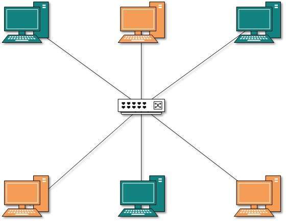
In this diagram, different VLANs are depicted in different color codes. Hosts in one VLAN, even if connected on the same Switch cannot see or speak to other hosts in different VLANs. VLAN is Layer-2 technology which works closely on Ethernet. To route packets between two different VLANs a Layer-3 device such as Router is required.